naca-wr-e-269

  • Version
  • 197 Downloads
  • 1.95 MB File Size
  • 1 File Count
  • April 15, 2017 Create Date
  • April 15, 2017 Last Updated
Scroll for Details

Sea-Level Performance Tests of a 22'' Diameter Pulse Jet Engine at Various Simulated Ram Pressures
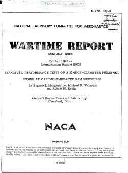
At the request of the Air Technical Service Command, Army Air
Forces, and the Bureau of Aeronautics, navy Department, an inves-
tigation is being conducted at the NACA Cleveland laboratory to
improve the performance and extend the operating life of the pulse-
Jet engine. As a part of this investigation, thrust-stand tests
were conducted to determine the sea-level performance of a 22-inch-
diameter pulse-Jet engine at simulated ram pressures of 0, 18, 40,
and 58 inches of water for the entire fuel-flow range of resonant
operation. The performance data obtained in these tests, which were
conducted from February to June 1945, are presented in this report.

Description ofgpulse:fiet engine and its operation. - The pulse-Jet
engine used in the investigation is a reproduction of the German engine
used in Wofld War II for propelling the V-l flying bomb. As illustrated
in the dimensioned sketch of figure 1, the pulse-Jet engine consists
of a flapper-valve grid assembly and a steel shell that forms the dif-
fuser entry ahead of the grid, the cylindrical combustion chamber, the
conical nozzle, and the long cylindrical tail pipe behind the grid.

The inner diameters of the combustion chamber and tail pipe are
21E and 155 inches, respectively; the ratio of combustion chamber to
tail-pipe flow area is therefore approximately 2:1. The flapper-valve
grid assembly consists of spring-steel sheets 0.010 inch thick, which
are preformed and installed to seat tightly against the ribs of the
aluminum grid sections. (See detailed sketch in fig. 1.) The spaces
between the ribs form the air passages across the grid sections; the
restriction of air flow through these passages is controlled by the
opening and closing action of the flapper valves. Three horizontal
venturi-shaped channels are located at the entrance to the combus-
tion chamber directly downstream of the'flapper-valve grid assembly.
The venturi channels are formed b the insertion in the forward end of
the combustion chamber of airfoil sections constructed of sheet metal.

FileAction
naca-wr-e-269 Sea-Level Performance Tests of a 22'' Diameter Pulse Jet Engine at Various Simulated Ram Pressures.pdfDownload 

Comment On This Post

Your email address will not be published. Required fields are marked *

naca-wr-e-269

  • Version
  • 197 Downloads
  • 1.95 MB File Size
  • 1 File Count
  • April 15, 2017 Create Date
  • April 15, 2017 Last Updated
Scroll for Details

Sea-Level Performance Tests of a 22'' Diameter Pulse Jet Engine at Various Simulated Ram Pressures

At the request of the Air Technical Service Command, Army Air
Forces, and the Bureau of Aeronautics, navy Department, an inves-
tigation is being conducted at the NACA Cleveland laboratory to
improve the performance and extend the operating life of the pulse-
Jet engine. As a part of this investigation, thrust-stand tests
were conducted to determine the sea-level performance of a 22-inch-
diameter pulse-Jet engine at simulated ram pressures of 0, 18, 40,
and 58 inches of water for the entire fuel-flow range of resonant
operation. The performance data obtained in these tests, which were
conducted from February to June 1945, are presented in this report.

Description ofgpulse:fiet engine and its operation. - The pulse-Jet
engine used in the investigation is a reproduction of the German engine
used in Wofld War II for propelling the V-l flying bomb. As illustrated
in the dimensioned sketch of figure 1, the pulse-Jet engine consists
of a flapper-valve grid assembly and a steel shell that forms the dif-
fuser entry ahead of the grid, the cylindrical combustion chamber, the
conical nozzle, and the long cylindrical tail pipe behind the grid.

The inner diameters of the combustion chamber and tail pipe are
21E and 155 inches, respectively; the ratio of combustion chamber to
tail-pipe flow area is therefore approximately 2:1. The flapper-valve
grid assembly consists of spring-steel sheets 0.010 inch thick, which
are preformed and installed to seat tightly against the ribs of the
aluminum grid sections. (See detailed sketch in fig. 1.) The spaces
between the ribs form the air passages across the grid sections; the
restriction of air flow through these passages is controlled by the
opening and closing action of the flapper valves. Three horizontal
venturi-shaped channels are located at the entrance to the combus-
tion chamber directly downstream of the'flapper-valve grid assembly.
The venturi channels are formed b the insertion in the forward end of
the combustion chamber of airfoil sections constructed of sheet metal.

FileAction
naca-wr-e-269 Sea-Level Performance Tests of a 22'' Diameter Pulse Jet Engine at Various Simulated Ram Pressures.pdfDownload 
17,005 Documents in our Technical Library
2759889 Total Downloads

Search The Technical Library

Newest Additions

NASA-RP-1060 Subsonic Aircraft: Evolution and the Matching of Size to Performance
AA-CP-20212-001
AA-CP-20212-001
ADPO10769 Occurrence of Corrosion in Airframes
The purpose of this lecture is to provide an overview ...
MIL-STD-1759 Rivets and Rivet Type Fasteners Preferred for Design
The purpose of this book form standard is to provide ...
MIL-STD-810G Environmental Engineering Considerations and Laboratory Tests
This standard contains materiel acquisition program planning and engineering direction ...