naca-tn-419

naca-tn-419
  • Version
  • 95 Downloads
  • 685.91 KB File Size
  • 1 File Count
  • April 23, 2016 Create Date
  • April 23, 2016 Last Updated
Scroll for Details

National Advisory Committee for Aeronautics, Technical Notes - Wind Tunnel Tests of the Fowler Variable Area Wing
naca-tn-419 Wind Tunnel Tests of the Fowler Variable Area Wing
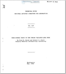
The lift, drag, and center'of pressure'charaCterisS
tics of a model of the Fowler variable—area wing_were
measured in the N.A.C.A. 7 by 10 foot wind tunnel. The
Fowler wing consists of a combination of a main wing and
an extension surface, also of airfoil section. The exten—
sion surface can be entirely retracted within the lowar
rear portion of the main wing or it can be moved to the
rear and downward. The tests were made with the nose
of the extension airfoil in various posit_ions near the
trailing edge of the main wing and with the surface at
various angular deflections. The highest' lift coefficient
obtained was CL = 5.17 as compared with 1.27 for the
main wing alone.
The Fowler wing, developed by Harlan D. Fowler. is
the result of an attempt to combine three different meth—
ods of increasing the maximum lift.
1. Increasing the area by means of an exten—
sion surface.
2. Increasing the effective camber by means of
a flap.
3. Providing a slot'to help maintain unburbled
flow at high angles of attack.
The combining of these methods is accomplished by means
of an extension surface, which .is a sort o_f flap having
an airfoil section. The extension airfoil is retracted
into the lower rear portion of the wing when not in use
but isaextended to the rear and dowuward when high lift
is desired. (Fig. 1.) The gap that is left between the
main wing and the extension airfoil forms a slot to main—
tain unburbled air flow over the rear airfoil at the high
angles of attack.
Previous wind—tunnel tests on models of 3-inch chord
at both Massachusetts institute of Technology and New York
University, and full—scale flight tee-ts have all shown ex—
ceptionally high lift coefficients with the Fowler wing
arrangement. (Reference 1. ) The present tests were made
as part of a series on high—lift devices in the 7 by 10
foot wind tunnel of the National Advisory Committee for
Aeronautics.~ The Clark Y airfoil section was used for
both the basic wing and the. extension airfoil. and the
tests were made to cover- a range. of slots and angular de-
flections of the extension airfoil.

FileAction
naca-tn-419 Wind Tunnel Tests of the Fowler Variable Area Wing.pdfDownload 

Comment On This Post

Your email address will not be published. Required fields are marked *

naca-tn-419

naca-tn-419
  • Version
  • 95 Downloads
  • 685.91 KB File Size
  • 1 File Count
  • April 23, 2016 Create Date
  • April 23, 2016 Last Updated
Scroll for Details

National Advisory Committee for Aeronautics, Technical Notes - Wind Tunnel Tests of the Fowler Variable Area Wing
naca-tn-419 Wind Tunnel Tests of the Fowler Variable Area Wing
The lift, drag, and center'of pressure'charaCterisS
tics of a model of the Fowler variable—area wing_were
measured in the N.A.C.A. 7 by 10 foot wind tunnel. The
Fowler wing consists of a combination of a main wing and
an extension surface, also of airfoil section. The exten—
sion surface can be entirely retracted within the lowar
rear portion of the main wing or it can be moved to the
rear and downward. The tests were made with the nose
of the extension airfoil in various posit_ions near the
trailing edge of the main wing and with the surface at
various angular deflections. The highest' lift coefficient
obtained was CL = 5.17 as compared with 1.27 for the
main wing alone.
The Fowler wing, developed by Harlan D. Fowler. is
the result of an attempt to combine three different meth—
ods of increasing the maximum lift.
1. Increasing the area by means of an exten—
sion surface.
2. Increasing the effective camber by means of
a flap.
3. Providing a slot'to help maintain unburbled
flow at high angles of attack.
The combining of these methods is accomplished by means
of an extension surface, which .is a sort o_f flap having
an airfoil section. The extension airfoil is retracted
into the lower rear portion of the wing when not in use
but isaextended to the rear and dowuward when high lift
is desired. (Fig. 1.) The gap that is left between the
main wing and the extension airfoil forms a slot to main—
tain unburbled air flow over the rear airfoil at the high
angles of attack.
Previous wind—tunnel tests on models of 3-inch chord
at both Massachusetts institute of Technology and New York
University, and full—scale flight tee-ts have all shown ex—
ceptionally high lift coefficients with the Fowler wing
arrangement. (Reference 1. ) The present tests were made
as part of a series on high—lift devices in the 7 by 10
foot wind tunnel of the National Advisory Committee for
Aeronautics.~ The Clark Y airfoil section was used for
both the basic wing and the. extension airfoil. and the
tests were made to cover- a range. of slots and angular de-
flections of the extension airfoil.

FileAction
naca-tn-419 Wind Tunnel Tests of the Fowler Variable Area Wing.pdfDownload 
17,005 Documents in our Technical Library
2820599 Total Downloads

Search The Technical Library

Newest Additions

NASA-RP-1060 Subsonic Aircraft: Evolution and the Matching of Size to Performance
AA-CP-20212-001
AA-CP-20212-001
ADPO10769 Occurrence of Corrosion in Airframes
The purpose of this lecture is to provide an overview ...
MIL-STD-1759 Rivets and Rivet Type Fasteners Preferred for Design
The purpose of this book form standard is to provide ...
MIL-STD-810G Environmental Engineering Considerations and Laboratory Tests
This standard contains materiel acquisition program planning and engineering direction ...