naca-report-378

- Version
- 323 Downloads
- 1.81 MB File Size
- 1 File Count
- August 25, 2016 Create Date
- August 25, 2016 Last Updated
National Advisory Committee for Aeronautics, Report - Comparison of Full Scale Properties Having RAF-6 and Clark Y Airfoil Sections
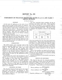
In this report, the efiiciencies of two series of pro—,
pellers having two types of blade sections are compared.
Sixfull—scale propellers were used, three having R. A. F.—6
and three Clark Y airfoil sections with thickness,‘chord
ratios of 0.06, 0.08, and 0.10. The propellers were tested
at fire pitch settings, which covered the range ordinarily
used in practice. These tests were conducted in the
Propeller Research Tunnel of the National Advisory
Committee for Aeronautics.
The propellers having the Clark Y sections gate the
highest pealc efiiciency at the low pitch settings. At the
higher pitch settings, the propellers with the, R. A. F.—6
sections gate about the same maximum efiiciency as the
Clark Y propellers and were more efioient for the condi-
tions of climb and take-of.
The airfoil sections most commonly used in this
country in propeller design are the R. A. F.—6 and
Clark Y. The following tests, which were made
incidental to some high tip speed propeller tests
(Reference 1) in the Twenty-Foot Propeller Research
Tunnel of the National Advisory Committee for
Aeronautics, afi‘ord an interesting comparison of these
airfoil sections as shown by the performance of full—
scale propellers.
Six propellers were used in this investigation, three
with R. A. Frfi and three with Clark Y sections.
The propellers of each group had thickness/chord
ratios of 0.06, 0.08, and 0.10. The airfoil sections
used on these propellers are not, strictly speaking,
Clark Y or R. A. F.—6 sections but are modifications
of these. However, in this report for the sake of
convenience, they will be referred to simply as Clark Y
and R. A. F.—6 sections.
The Propeller Research Tunnel and its test equip-
ment have been described in Reference 2. The
propellers were driven by a 435—horsepower Curtiss
D—l2 engine, mounted in an open-cockpit tractor
body as shown in Figure 1.
| File | Action |
|---|---|
| naca-report-378 Comparison of Full Scale Properties Having RAF-6 and Clark Y Airfoil Sections.pdf | Download |
Comment On This Post