17,005 Documents in our Technical Library
2439896 Total Downloads

Newest Additions

NASA-RP-1060 Subsonic Aircraft: Evolution and the Matching of Size to Performance
AA-CP-20212-001
AA-CP-20212-001
ADPO10769 Occurrence of Corrosion in Airframes
The purpose of this lecture is to provide an overview ...
MIL-STD-1759 Rivets and Rivet Type Fasteners Preferred for Design
The purpose of this book form standard is to provide ...
MIL-STD-810G Environmental Engineering Considerations and Laboratory Tests
This standard contains materiel acquisition program planning and engineering direction ...

naca-rm-a8a20

  • Version
  • 104 Downloads
  • 1.85 MB File Size
  • 1 File Count
  • April 20, 2017 Create Date
  • April 20, 2017 Last Updated
Scroll for Details

National Advisory Committee for Aeronautics, Research Memorandum - An Investigation of Submerged Air Inlets on a Scale Model of a Typical Fighter Type Airplane
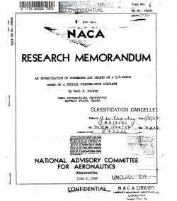

Wind—tunnel tests were made of submerged air inlets on the
fuselage of a l/ll—scale model of a typical fighter—type airplane.
The results are presented for ramp plan forms with parallel and
with diverging walls and show the effect of the duct-entrance
location (forward of the wing and. over the wing), internal ducting
efficiency, and deflectors.

ILEhe air inlets having the ramps with diverging walls were satis-
factory in both locations tested. on the fuselage, providing high ram
pressure recoveries at the simulated entrance to the compressor, high
predicted critical Mach numbers, and low external drags. The submerged
air inlets with parallel ramp walls had lower ram pressure recoveries
for the normal operating range. The ram pressure recovery ratios
measured at the inlets were higher for the forward location of the
inlets than for the aft location. For an assumed engine position,
however, the aft location of the inlets with the shorter, more
efficient internal ducts gave the higher ram recoveries at the
simulated compressor for the test conditions.

The early development of NACA submerged air inlets was conducted
with the submerged inlets installed in the flat wall of a wind
tunnel (references 1 and 2). The results of these tests indicated
that it should be feasible to design an efficient air—induction
system with twin submerged inlets. installed on the sides of the
fuselage. Placing the submerged inlets on the sides of the fuselage
ahead of the Jet engine results in a short, straight internal
ducting system (references 3 and 1L). As the submerged inlets will
not protrude outside of the basic fuselage contour they should tend
to elnminate, by inertia separation, foreign material (shell cases,
rocks, hail, etc.) from the air inducted into the motor.

The results of reference 3 indicate that the relative location
of the wing and the submerged inlets might be critical for inlet
performance. The purpose of the tests presented in this report was
to investigate the effect of the location of the duct inlets on
their characteristics; Two locations were tested, one forward of
the wing where.the fuselage boundary layer was thin, and the other
farther aft on the fuselage and over the point of maximum thickness
of the wing. The model was constructed so that, in later tests,
the effect of a tractor prOpeller on the ram recovery could be
determined.

FileAction
naca-rm-a8a20 An Investigation of Submerged Air Inlets on a Scale Model of a Typical Fighter Type Airplane.pdfDownload 

Comment On This Post

Your email address will not be published. Required fields are marked *

naca-rm-a8a20

  • Version
  • 104 Downloads
  • 1.85 MB File Size
  • 1 File Count
  • April 20, 2017 Create Date
  • April 20, 2017 Last Updated
Scroll for Details

National Advisory Committee for Aeronautics, Research Memorandum - An Investigation of Submerged Air Inlets on a Scale Model of a Typical Fighter Type Airplane


Wind—tunnel tests were made of submerged air inlets on the
fuselage of a l/ll—scale model of a typical fighter—type airplane.
The results are presented for ramp plan forms with parallel and
with diverging walls and show the effect of the duct-entrance
location (forward of the wing and. over the wing), internal ducting
efficiency, and deflectors.

ILEhe air inlets having the ramps with diverging walls were satis-
factory in both locations tested. on the fuselage, providing high ram
pressure recoveries at the simulated entrance to the compressor, high
predicted critical Mach numbers, and low external drags. The submerged
air inlets with parallel ramp walls had lower ram pressure recoveries
for the normal operating range. The ram pressure recovery ratios
measured at the inlets were higher for the forward location of the
inlets than for the aft location. For an assumed engine position,
however, the aft location of the inlets with the shorter, more
efficient internal ducts gave the higher ram recoveries at the
simulated compressor for the test conditions.

The early development of NACA submerged air inlets was conducted
with the submerged inlets installed in the flat wall of a wind
tunnel (references 1 and 2). The results of these tests indicated
that it should be feasible to design an efficient air—induction
system with twin submerged inlets. installed on the sides of the
fuselage. Placing the submerged inlets on the sides of the fuselage
ahead of the Jet engine results in a short, straight internal
ducting system (references 3 and 1L). As the submerged inlets will
not protrude outside of the basic fuselage contour they should tend
to elnminate, by inertia separation, foreign material (shell cases,
rocks, hail, etc.) from the air inducted into the motor.

The results of reference 3 indicate that the relative location
of the wing and the submerged inlets might be critical for inlet
performance. The purpose of the tests presented in this report was
to investigate the effect of the location of the duct inlets on
their characteristics; Two locations were tested, one forward of
the wing where.the fuselage boundary layer was thin, and the other
farther aft on the fuselage and over the point of maximum thickness
of the wing. The model was constructed so that, in later tests,
the effect of a tractor prOpeller on the ram recovery could be
determined.

FileAction
naca-rm-a8a20 An Investigation of Submerged Air Inlets on a Scale Model of a Typical Fighter Type Airplane.pdfDownload 
17,005 Documents in our Technical Library
2439897 Total Downloads

Search The Technical Library

Newest Additions

NASA-RP-1060 Subsonic Aircraft: Evolution and the Matching of Size to Performance
AA-CP-20212-001
AA-CP-20212-001
ADPO10769 Occurrence of Corrosion in Airframes
The purpose of this lecture is to provide an overview ...
MIL-STD-1759 Rivets and Rivet Type Fasteners Preferred for Design
The purpose of this book form standard is to provide ...
MIL-STD-810G Environmental Engineering Considerations and Laboratory Tests
This standard contains materiel acquisition program planning and engineering direction ...